Harmonic Gear

Strain Wave Gear Principle
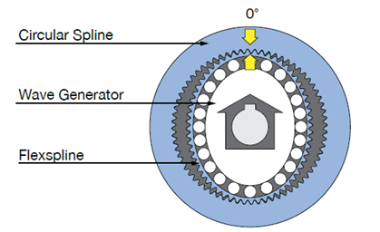
Harmonic Drive® strain wave gearing utilizes a unique operating principle which is based upon the elastic mechanics of metals. The greatest benefits are the zero-backlash characteristics and the weight and space savings compared to other gears because our gear mechanism consists of only three basic parts. They are the: Wave Generator, Flexspline and Circular Spline.
This simple three element construction combined with the unique operating principle allows extremely high reduction ratio in a very compact and lightweight package. Neither the size nor weight of the gear vary with the reduction ratio. The high performance attributes of this gearing technology including zero backlash, high torque, compact size, excellent positional accuracy and repeatability are all a direct result of the unique operating principle.
The Components
Wave Generator

The Wave Generator is comprised of a specially designed thin raced ball bearing that is fitted onto an elliptical hub. This serves as a high efficiency torque converter and is used as the input of the gear and is connected to the motor shaft. The outer surface of the Wave Generator plug has an elliptical shape that is carefully machined to a precise specification. The Wave Generator is typically used as the input, usually attached to a servo motor.
Flexspline

The Flexspline is a thin cylindrical cup made from alloy steel with external teeth on the open end of the cup. The Flexspline is radially compliant but torsionally is very stiff. When the Wave Generator in inserted into the Flexspline the gear takes on its elliptical shape. The Flexspline is used as the output and is connected to the output flange.
Note: Although the steel Flexspline flexes during normal operation, there is no concern about fatigue failure. The stresses developed are far below the endurance limit of the material. Thus the Flexspline will achieve infinite life when used according to catalog ratings.
Circular Spline

The Circular Spline is a rigid ring with internal teeth. When the gear is assembled it engages the teeth of the Flexspline across the major axis of the Wave Generator ellipse. This engagement is like an ellipse inscribed concentrically within a circle. Mathematically, an inscribed ellipse will contact a circle at two points. However, the gear teeth have a finite height. So there are actually two regions (instead of two points) of tooth engagement. The Circular Spline has two more teeth than the Flexspline and is fixed to the gear housing.
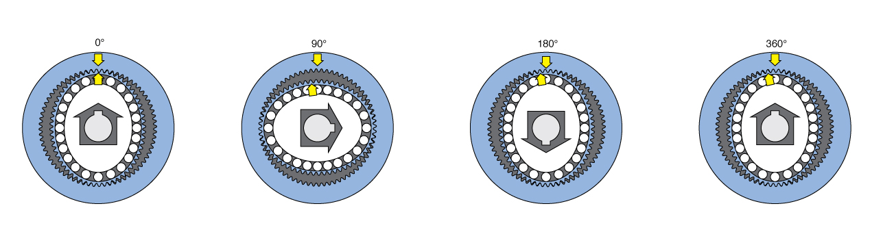
How it Works
Below is an exaggerated two-dimensional diagram demonstrating how the three gear elements engage and rotate.
The Flexspline is slightly smaller in diameter and has two fewer teeth than the Circular Spline. The elliptical shape of the Wave Generator causes the teeth of the Flexspline to engage the Circular Spline at two opposite regions across the major axis of the ellipse. For every 180 degree clockwise rotation of the Wave Generator the Flexspline teeth are advanced counterclockwise by one tooth in relation to the Circular Spline. Each complete clockwise rotation of the Wave Generator results in the Flexspline moving counter-clockwise by two teeth from its original position relative to the Circular Spline. Because the gear teeth are always fully engaged in a region along the major axis, Harmonic Drive® strain wave gearheads have Zero Backlash.
Superior Gear Performance Using an S Tooth DesignHarmonic Drive developed a unique gear tooth profile that optimizes the gear tooth engagement. It has a special curved surface unique to the S tooth profile that allows continuous contact with the tooth profile. It also alleviates the concentration of stress by widening the width of the tooth groove against the gear tooth thickness and enlarging the radius on the bottom. This tooth profile enables up to 30% of the total number of teeth to simultaneously. Additionally the large tooth root radius increases the tooth strength compared with an involute tooth. This technological innovation results in high torque, high torsional stiffness, long life and smooth rotation.
|
||||||
|
||||||
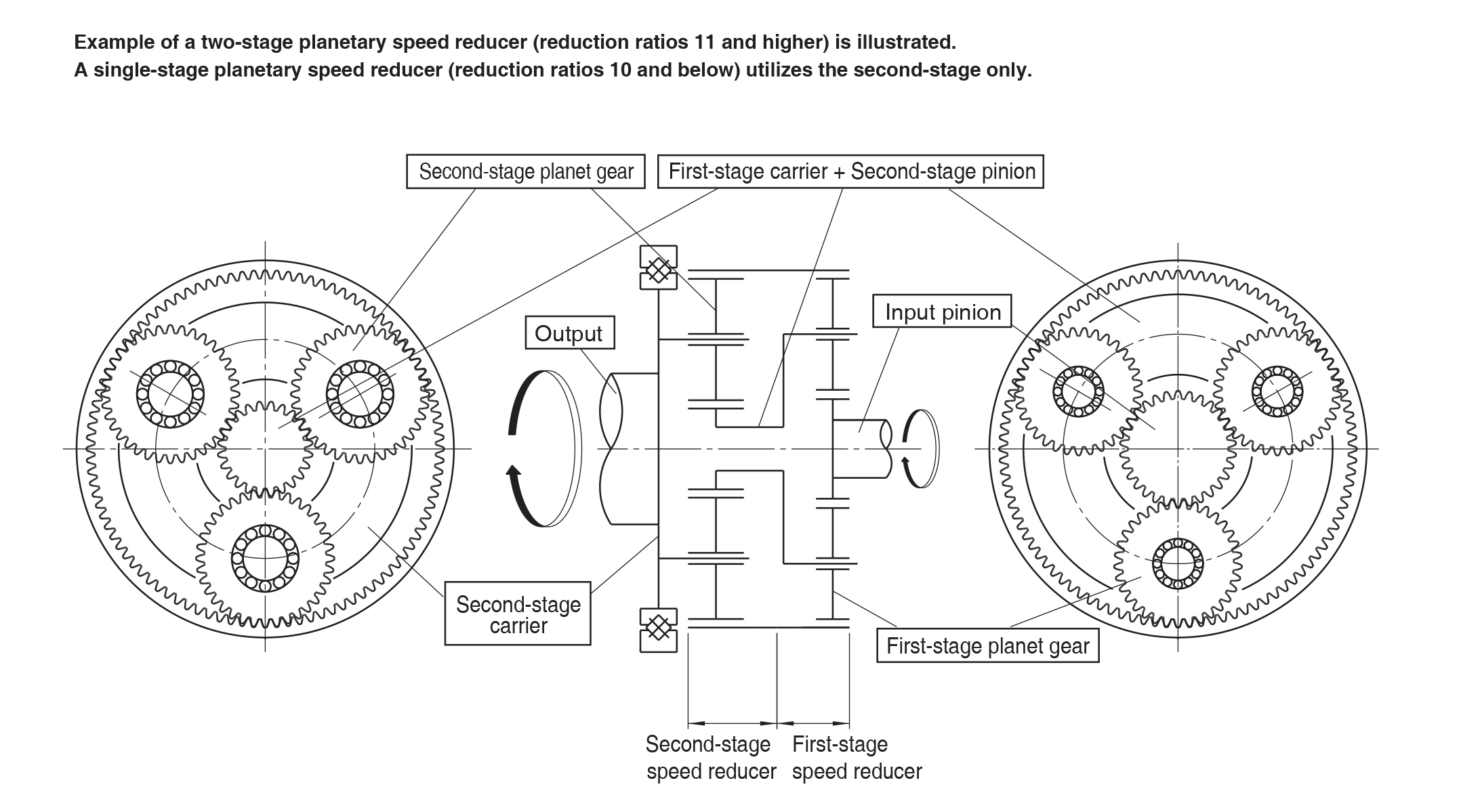
Planetary Gear PrinciplePlanetary gears have simultaneous meshing between the sun gear and planet gears and between the planet gears and the internal gear. The sun gear is connected to the motor and a carrier, supporting the planet gears, is connected to the output. Single stage planetary gears can achieve reduction ratios up to 10:1. Ratios above 10:1 utilize a two stage design where the carrier of the first stage drives the sun gear of the second planetary stage. |
||||||
Harmonic Planetary Operating Diagram
First StageRotation of the input pinion transfers revolution motion to the first-stage planet gears that mesh with it. The motion is then transferred to the first-stage carrier through the planetary shaft to the second-stage pinion. The direction of rotation of the first stage carrier is the same as the input pinion. Second StageThe second-stage pinion gear is driven by the first-stage carrier and provides the input to the second-stage planet gears. Similar to the first-stage, the rotation is then transferred to the second-stage carrier. The second stage carrier serves as the output of the gearhead. The direction of rotation of the second stage carrier is the same as the input pinon. |
||||||
How Harmonic Gearing Works |